When approaching a texturing job, the first thing to think of is what your final output will be. Something that is rendered in Maya is going to use very different techniques from something being exported to a game. It is important to note that depending on what your end goal is, you may not be able to use to all the possible customizations we will discuss in this lecture.
When using Maya's simplest renderer; the Software renderer, you can add color, add shine, add transparency, and more, to your heart's content. If you use Arnold, a more advanced renderer that comes with Maya, even more advanced features are available such as sub surface scattering and global illumination.
Nevertheless, if you are exporting to another software package or game engine, you are generally limited to the kind of data that is transferable or supportable. As game engines become more complex, they support more features, with modern engines capable of supporting even advanced techniques and elaborate custom shaders. Usually when exporting to a real time engine you are creating a set of images and then linking up those images to the appropriate channels in the engine specific shader.
|
|
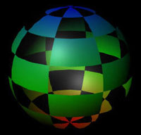
This slimy looking stuff is just a simple noise image applied to a flat plane. The attributes and what it is connected to change it from a flat image into 3D goop.
|
This lecture will focus on the texturing tools in Maya, renderable attributes in Maya, and using basic image maps to control those attributes.
Getting Your Work Out of Maya
The first part of texturing is actually lighting. Although texturing and lighting seem like two different things, they are actually intertwined. Think of it this way: When you look at an object, three things are
happening. First, light is coming from some source. Then it is hitting an object and changing its properties based on what it hit. And finally, it reflects back into our eyes. In other words, what we see is a combination of the properties of light and the properties of the surface. Therefore, the light we use in our scenes can drastically affect the way our surfaces look, since it alters our starting point. It's like painting on different sheets of colored paper. Depending on the surface used, the same paints will come out as different colors.
|
|
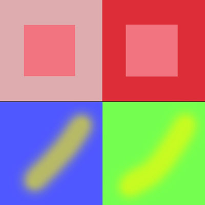
Color is relative. The center square in both top cubes is the same, but appears different because of adjacent color. On the bottom, both brush strokes are the same color, but they appear to be different colors because of the surfaces they are on.
|
Lights and Light Rigs
Because of the way that light interacts with color and with surfaces, and because some software features like bump mapping and reflectivity depend on the direction of light, it helps to do your lighting and texturing in tandem as much as possible. When texturing an object that will be seen under many different lighting conditions, creating a neutral light setup, or experimenting with a few different setups, can be helpful. The collection of lights being is used to illuminate your model is commonly referred to as a light rig.
In order to make a light rig, we need to understand the various kinds of lights. I'm going to go ahead and create some primitives so we can see the effects of the lighting, and you should too.
I'll press 7 to tell my view to Use All Lights in determining my real time shading. This turns my object temporarily black, as I have no lights in my scene. (No light = No see, just like in the real world.)
The simplest kind of light is a directional light. To create one, use the Create > Lights menu, or click the Rendering tab on the shelf (remember, if you don't see all of the tabs, click the little tab icon on the far left), and then click the Directional Light icon.
Now your object will be lit from one direction. A directional light produces a wash of light from one direction, much like the sun. This evenly illuminates everything in your scene from one direction. Note that the far side of the object has no illumination whatsoever.
|
|
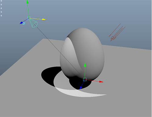
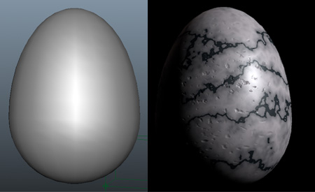
Egg and its surface with a directional light
|
By default the real time lighting display mode doesn't show shadows from our lights, but you can turn them on using the tiny, tiny button on the viewport.
When using default Maya lights and the software renderer, light does not automatically bounce and
fill a scene with ambient light like it does in the real world. This is usually true in most real time
applications as well. This means that any side of an object that doesn't directly receive light will stay
black. Let's make a new light to help with this.
Click the Spotlight icon  , or use the Create > Lights menu to create a spotlight. Spotlights produce
light in a cone shape, as you'd expect. To manipulate the spotlight, we are going to use the Show
Manipulator. Activate this by pressing the T key.
, or use the Create > Lights menu to create a spotlight. Spotlights produce
light in a cone shape, as you'd expect. To manipulate the spotlight, we are going to use the Show
Manipulator. Activate this by pressing the T key.
The Manipulator is a special case tool that changes for each object you select, and allows you to change certain attributes in a visual manner. For now, it will show a handle for the light, and a handle for the target of the light. Grab the target and drag it down to your object. You'll see the effect of the light on your object as you swing the target around.
|
|
Spotlight on the egg and surface |
Use multiple views if you have any trouble getting your spotlight visible—if
your light target is positioned under your main surface, you won't see any
change.
Now that the object is illuminated from two sides, it becomes necessary to
adjust the qualities of each light so that it doesn't become washed out. We
will pick one light to be our main light, or key light.
In this case, I'll choose the directional light. The spotlight will fill in the dark
areas—we will call it our fill light.
Click the directional light to select it and open up the Attribute Editor (Ctrl+A).
Here we can adjust the color and intensity of the light. Click the white box
next to Color under the Directional Light Attributes. In the Color Chooser
that appears, I choose RGB from the left menu at the bottom, and 0 to 255 from
the right menu. Then I set the color to a very light blue (240, 240, 255 RGB
values) because sunlight is actually slightly blue.
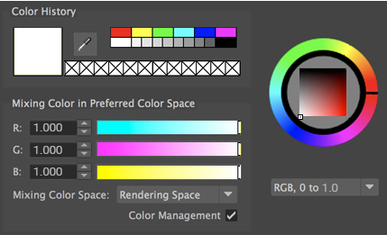 |
| A very small amount of blue is sufficient to change the tone of the light dramatically. |
Now select the spotlight and return to the Attribute Editor. The spotlight I'll change to a much lower intensity, like 0.3, as it represents reflected light. I'll adjust my Penumbra angle up to 20 or so. Penumbra is the distance at which the light border goes from full strength to zero strength. High values soften the border of the light dramatically.
We only want shadows coming from obvious light sources, and this light is just intended to fill in dark areas, so under the Shadows tab, I will turn off Ray Trace shadows. This will make my darker areas different, but still illuminated. Here's a render that makes things look a bit more filled out and interesting:
The third kind of light I'll introduce is the point light. A point light emits light in all directions, like a bulb. The farther away from the light, the darker it gets. Our scene, lit only with a point light, looks like this:
|
|
A
single low bulb light produces a moody noir look due to the fast falloff.
|
Cameras
In order to render something, Maya needs a view to render from.
Maya scenes come with four default cameras: Top, Side, Front, and Persp. While
you can use any of these to render from, it helps to create a fifth. Then you
can use the default views to work in, and leave your main view alone.
To create a camera, click the camera icon  ,
or choose Create > Cameras > Camera. A
new camera will appear, and you can position it anywhere you want using controls
similar to those of the spotlight. To view through the camera, choose Panels > Perspective > yourCameraName from
the menu bar above one of your views. Cameras have many attributes, but you
only need to worry about a few for now:
,
or choose Create > Cameras > Camera. A
new camera will appear, and you can position it anywhere you want using controls
similar to those of the spotlight. To view through the camera, choose Panels > Perspective > yourCameraName from
the menu bar above one of your views. Cameras have many attributes, but you
only need to worry about a few for now:
 |
|
 |
| |
-
Focal Length: 50mm is about the
focal length of a human eye. Smaller than this is a wide-angle lens,
which will make things appear smaller, with a greater perspective. Longer
is a zoom lens, which flattens things out.
-
Environment: The background color of your camera when you render. Adjust this for personal preference—what's generally used is black, white, or sky blue.
-
Output Settings: Make sure Renderable is checked.
|
|
 |
|
 |
Once you have your camera placed, it often helps to lock it so that you don't accidentally move it and have trouble returning to your desired view. To lock a camera (or any transform node), select the attributes in the Channel Box and right-click and choose Lock Selected.
Rendering is the act of creating an image or movie from your Maya file. Rendering is the only way to see your scene properly, as the real-time display will only show certain information and low-quality previews. Even if your model is intended for export to a real-time engine, you can use the rendering engines to bake details and lighting into your textures that might not be available or would be too slow
for your real-time engine.
|
|
The egg as it appears in Maya (left) and as it appears when rendered (right). |
The easiest way to get a quick look at your scene is to click the Render Frame icon (Red).
This will render a view of your scene from the current camera, and bring it up in a new window, the Render View. If you have not already changed your default Renderer from Arnold to Maya Software, things might appear different (or black). We will talk about Arnold a little bit later in this lesson.
|
|
The render view lets you see your scene output with more than just Viewport 2.0 can display. |
You can now adjust your scene and re-render from this view. You can use the Render Region function to render just a small area if render times are high. To change the resolution, click the Render Options icon (Blue in the above image) . This brings up your render settings. Here you can change the resolution, image output, and so forth. For instance, if you later wish to render out a movie or sequence, you need to change the Frame/Animation Ext to something that's not "[Single Frame]".
The Maya Software tab contains render engine-specific settings. Here you can turn up your antialiasing
settings, as well as turn on raytracing. Raytracing is needed for some features mentioned below.
Texturing is an art, so there is no one right
way to texture things. In fact, there are many ways to texture things in
Maya, and many options for each approach to texturing. This course will focus
on using image maps, as this is the most widely used method for games and
film alike. However, since many of the other ways are great for producing
rendered content, we'll go over all the ways to skin your model, be it a cat,
dog, or multi-tentacled monster from the abyss.
Hypershade: A Texture Artist's New Home
Let me introduce your new best friend: the Hypershade window.
The Hypershade is a mess: bloated, complicated, and slow. Like your best friend,
though, it has some redeeming qualities that
keep you spending time together. Hypershade offers quick access to creating
textures, as well as visual ways to represent those textures. Go to Window > Rendering
Editors > Hypershade and let's take a quick look at the various
options.
Don't worry if some of this gets confusing—we'll
try out the most important features after our tour.
Here's a guide to the different areas. We'll start with the Work Area, bottom
right:
|
|
|
| |
-
Browser: This area is where you can navigate the existing shading nodes in your scene. Nodes are organized into types: Materials, Textures, Lights and so forth so you can easily find the one you are looking for and select it, or place it in the Node Graph.
-
Create: This is where you can find new nodes to make and integrate into your shading network. These are materials, textures, and blending nodes, as well as all sorts of special purpose stuff.
-
Node Graph: This is where the much of the work happens. Connections between nodes from the browser or create area are made here, and you can view and edit them using this window.
-
Property Editor: Where the other half of the work happens. This is basically the attribute editor but stuffed into a corner. You can make new nodes and connections here as well by
clicking on the checker boxes and following the prompts.
-
Viewer: This just shows your material on a few generic objects. Generally speaking this isn't too useful since what we really care about is how our material looks on a specific object, but it can give you a ballpark.
|
|
|
|
|
And because everyone likes memorization, here are some definitions to think about as we start talking about these textures, shaders, and so forth.
|
|
|
| |
-
Material: A node that encapsulates texture data. The material determines what attributes a surface has, most notably its shininess. Any given polygon can only have one kind of material assigned to it at a time. (A material is also called a shader.)
-
Texture: A node that contains color or value information, such as an image file or procedural noise. Textures are used as inputs for materials to give greater control or detail. They come
in two varieties: 2D and 3D.
-
Utility: Nodes that alter materials or textures with some special function, such as blending, limiting, multiplying, or inverting.
-
Shading Network: The whole collection of Materials, Textures, Lights, and Utilities used to determine the actual final look of a surface. These are represented in the Hypershade as a graph of nodes and lines.
|
|
|
|
|
Not Sunglasses, But Still Cool
|
|
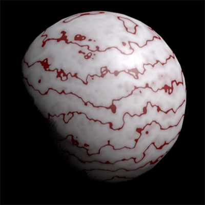
This detailed marble egg has a fairly simple mathematical texture on it.
|
Go ahead and open up the Hypershade window if it's not already open (Window > Rendering Editors > Hypershade). On the left, you'll see the Create tab with a bunch of surfaces underneath it. Clicking any of these surfaces will create a new Material node that you can then assign to an object. Let's run down the common ones:
|
|
|
| |
-
Lambert: The most basic material. It has a flat, diffuse look. The default texture is a gray lambert.
-
Phong: Phong adds hard specular highlights (bright spots) and reflectivity into the mix. Phong surfaces are good for hard, shiny surfaces such as glass.
-
Phong E: A simpler, and therefore faster, rendering version of Phong.
-
Blinn: The most frequently used, Blinn materials have soft speculars, and are less likely to produce artifacts or noise when used with high-frequency textures. Well suited to metallic objects.
-
Anisotropic: A material that represents surfaces with micro grooves in them, such as CDs or shiny fabrics. The specular highlight in an anisotropic can be given a direction that matches the direction of the grooves in the surface.
|
|
|
|
|
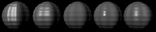
|
|
Unaltered materials. From left to right, Anisotropic, Blinn, Lambert, Phong, Phong E.
|

Assigning Materials
Let's assign a material to an object. Click Blinn in the Create tab. A new node, blinn1, appears in the Browser, the node graph, and is highlighted in the Property Editor. In the property editor, change the Color to blue. You should see material appearance change in the Viewer. Now select an object in your scene. Right-click on the material node in the Hypershade window, and select Assign Material to Selection from the marking menu. Alternatively, you could drag and drop your material onto your object using the middle mouse button, or select Assign Existing Material from the Lighting/Shading menu (this menu is at the top of the screen when "Rendering" is selected from the upper-left dropdown).

|
New material
|
Congrats, your first textured object! Blue plastic! Now, let's make things a bit more complicated and create a little shader network. In the Attribute Editor for your blinn1, click the checkered box  by the Color slider. The Create Render Node window pops up, waiting for you to select the kind of Texture node you want to connect to this Material node. Choose Marble, down towards the bottom of the 3D Textures section. Now your object is red white with red streaks. You can render if you want and see the difference between the real time display and the rendered image.
Now select the blinn1 tab again, and this time click the box near Transparency. Transparency, like most of the non-color attributes, is based on the value of the texture—in other words, how black or white it is. Areas that are white are transparent, areas that are black are not. Gray areas are somewhat transparent. Select a checker pattern, which defaults to black and white. Now your model has cut out holes in its rainbow self.
Shader Networks
Shader networks that are made like this out of computer-generated textures, are called procedural textures. They have the advantage of being of infinite resolution (they render fine no matter how big or close they get) and infinitely repeatable. They also can sometimes be used without UV's which can be a huge timesaver as you'll learn later. However, they can be complicated to set up or not as precise as using pre-generated images (image maps, our next topic). They also generally do not export well from
Maya.
|
|
This torus gains complexity through the addition of more procedural textures to its shading network.
|
Generally, the procedure for building a procedural texture is to create nodes and drag them into
various attributes of the material you are building. One texture for color, one texture for specularity,
one for surface normals, and so on. Sometimes you might want to put one texture into another, like in
the above torus. The networks can quickly build and get complicated, but the possibilities are limited
only by your patience.
|
|
The shading network for the torus above. A granite drives one half of a stucco which drives the color and bump values of the blinn.
|
Image Maps
The most common way to texture an object, and certainly the best way to texture a model with as simple a texture as possible, is to use image maps. Image maps usually use a bitmapped image that supports transparency, like a .PNG, .TIFF, or .EXR, although simple .JPGs are also possible.
|
|
This image is just a 2 poly plane, with a few image maps applied to it. The illusion of depth and shininess comes from bump and specular maps.
|
You can map an image to anything you could map a procedural texture to: color, bump, specular, transparency, and so on. Again, maps that are not color instead use the value of the image, and therefore they are often grayscale.
|
|
The quick bump map I made for the previous image. Click it to download a large version.
|
Creating an Image Map
To create an image map, start with your source, be it a photograph, scan, or a hand/computer generated image. Load it into Photoshop. I usually adjust the Levels to ensure that the image takes full advantage of the range (0-255). This is especially important for grayscale maps, which rely on only one channel to create contrast. If your image only has pixels in the 35-200 range, you are wasting a good percentage of your possible contrast, and therefore detail. The best options are usually powers of two,
usually square (for example, 1024x1024). Then, save your image out in the proper format. Maya supports almost all image formats, including .PSDs, and its own format, .IFFs. It is important to note what bit depth you are saving at, however. If your image has an alpha channel (discussed later) you must save a 32 bit image. Also, make sure your format supports alphas (.TIFs, .TGA, .PNG, .IFF, and a few
others do). If your image is just color (or gray), choose 24 (or 8, for gray). Name your images appropriately, and you are ready to apply an image map.
Before we apply an image map, the attribute must have an open connection. If you've applied a texture to this channel of your material previously, the existing connection must be removed. There are several ways to do this. Selecting the connection itself in the work area of the Hypershade window (the colored lines) and deleting them will work. This preserves both nodes, and leaves them in the work area to use later. If you do not want the node at all, you can select and delete it--this will also break the connection, of course. Lastly, you can right-click the attribute name in the propert editor and select "Break Connection" from the pop up menu.
|
|
|
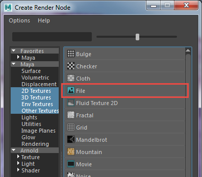
To apply an image map, click the checkered box next to the color slider again, but choose a File texture under 2D Textures.
|
|
|
|
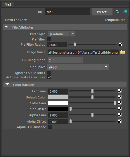
The file node contains the link to your actual image.
|
Choosing File will ensure your map gets applied in the usual fashion. Next, you have to select a file for this File node. Click the folder near the Image Name field, and browse for your favorite photo. Apply your material to your object, and unless it's a plane you probably have a funky looking object with a photo smeared or repeated across it. (Can't see it? Give it a render to check it out!)
|
|
|
This text is nearly unreadable because of distortion
|
Rather disappointing really, after all that effort. But don't worry. The reason the image is distorted is because Maya doesn't know how to ideally place your image on the object. That data is controlled by something called UVs, and we will get into those in the next lecture. Don't fear though, we can proceed by practicing on a plane, because a plane comes with UV's that are square and regular and will display our image maps without distortion.
|
|
A poly plane has undistorted checkers, while the sphere gets pinching near the poles and fat
around the center.
|
A few things to note here: You can apply any image to any attribute that sports one of those little boxes. However, applying a color image to almost any attribute besides color will only use the value of the image (the V on the HSV scale). In other words, it converts the image to grayscale. It's usually best to have your own grayscale image that you can adjust separately for grayscale-requiring attributes.
Texture Attributes
Image maps can give you a great deal of control over your surface, but like any source of power, image maps can be problematic without proper control. So to prevent things from getting outta hand (next stop, world domination?), let's cover the attributes you might want to control for your exercise. That way, you'll know what to do with your maps.
|
|
|
| |
-
Color: Just what it says—the diffuse color of the object. This is the underlying palette Maya uses when determining what color each pixel of the object will be. This color is then adjusted by other attributes, such as light levels or transparency, to yield the final pixel.
-
Transparency: Another fairly straightforward one. Light parts make things go clear, dark parts keep them opaque. Transparency does not denote volume, so sharp holes in objects appear like thin shells instead of deep holes. Parameters like specular and reflectivity are unaffected by transparency, as it only affects the diffuse color of the object.
- Specular: The specular highlight of an object is actually an artificial reflection of a bright light source: a hotspot. Turning this on makes objects look shiny, reflective, or metallic. A small, bright hotspot indicates a very smooth surface. Metal specular highlights tend towards the diffuse color of the object, while most other objects are white (or the color of the light causing them). Specular is a great, fast way of faking some reflection for a fraction of the render cost. You can load up a grayscale specular map in the Specular Color field of the Attribute Editor for your shader.
|
|
Without specular (top) and with (bottom)
|
-
Normal/Bump: Normal and Bump maps are an illusion designed to make surfaces look more detailed than the underlying geometry. These create shading on a surface that makes
part of the surface look raised or lowered. A normal map is like a fancy bump map that operates on all three axis instead of just perpendicular to the surface. Normal maps are extremely common ways of creating the appearance of additional detail without needing extra geometry.
The effectiveness of a bump depends on the viewing and light angles. Very large bumps tend to break down and look cruddy, so bump maps are best kept to low values (a Bump
Depth of 0-2) and used on small details, like bricks or scratches. Bumps create a separate node in your network.
|
|
Without a diffuse map (top) and with (bottom)
|
-
Reflectivity: Just as it sounds, reflectivity controls how reflective an object is, from 0 (0 percent) to 1 (100) percent, or mirrored. Reflectivity requires raytracing, and is thus very slow to render. Reflectivity maps are usually used to turn off or on reflectivity in areas where it is needed: To ensure that dirt on a mirror does not reflect, or that only the visor and metal on a character do reflect.
- Diffuse: Diffuse is the tendency of light to scatter when it hits an object. Low diffuse values scatter lots of light, making surfaces darker and more absorbent. Coal is a good example of this. High diffuse values reflect a lot of light, making surfaces brighter. Diffuse maps are great for adding dirty looks to things, and shadowing cracks in conjunction with
bump maps. For example, when a rock gets wet and appears darker, its is because the diffuse property of the surface has changed with the addition of water to reflect more light away and scatter less.
|
|
|
|
|
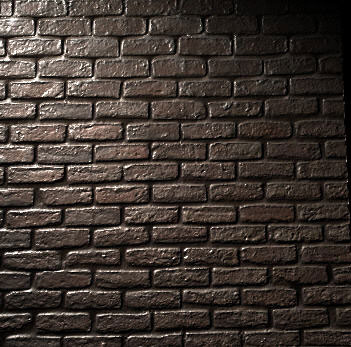
How the Wall is Built
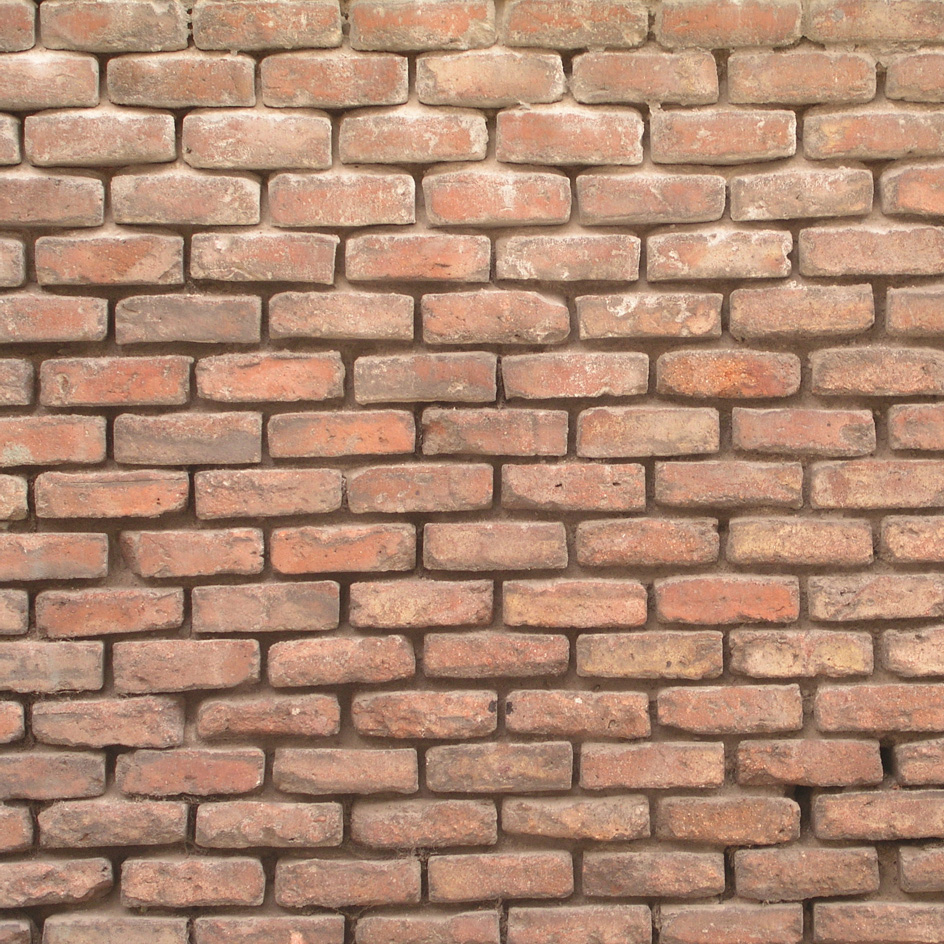
A complete texture might have maps for several of these. Take the wet brick wall for instance. This brick wall needs a picture of brick for the color map. Then a grayscale image version of that map where the mortar is made dark can be applied as a bump. This "pushes" the mortar in and creates texture on the bricks. A second grayscale map can be applied as a specular map to make the wetter areas shinier. If there were puddles, a reflection map might help them look more realistic by adding reflections just to the puddles.
Sometimes, you can get away with using the same maps for more than one purpose. Sometimes you can't, due to differences in the surface or incompatibilities (you want detail in one map that cannot be in the other, or the dark/light values need reversing in a certain area, for instance)—in which case, getting off your lazy duff and making a new version is the only option.
|
|
The same image file is used for bump and diffuse here, as well as reflectivity.
|
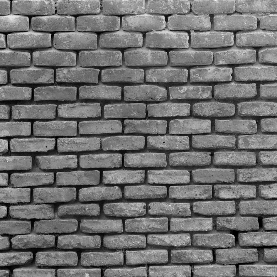
In the above examples, I only used two different image files, a color map and a grayscale map that I used as bump/specular/diffuse as needed. The grayscale map is a version of the color map with levels adjusted and the mortar darkened slightly. This preserves some of the small detail, and since the mortar was naturally dark, it was easy too!
Above you can see the color image file is used in the color channel, the grayscale is used in the diffuse channel unaltered. It also runs into the Normal Camera channel as a bump node. This node is automatically generated when connecting the file from the property editor, and is used to package up the data from the image in a way that the Normal Camera input expects. Lastly the grayscale image is run through a blend utility node, which blends it with black to make it darker instead of altering the image in Photopshop. The output of that node controls the reflectivity, essentially making the object less reflective than the grayscale image alone would have.
Making Normal Maps
A normal map is a great way of adding in tons of apparent detail to a model without actually having to increase your poly count. Unfortunately, a normal map is not just a simple black and white image that can be painted by hand. Nitty gritty technical stuff warning: A normal map uses RGB pixels as a vector indicator of the direction of the surface. This is why it is superior at altering the appearance of the model from a bump map. However, it means the maps are lovely purply-opalescent things that are extremely difficult to edit by hand. It must be extracted from a comparison between two different geometries.
|
|
Normal map for a game character.
|
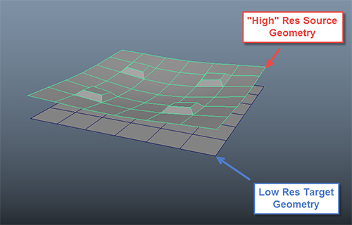
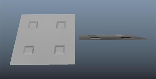
Let's make our first normal map, using a basic plane and some extra geometry. First, I'm going to make a low resolution version of my model, which in the case of the plane should be super easy. I'll just make a plane with a few cross sections. This is my target geometry, where I want to place my new normal map and make it look snazzier. To bring the snazzy, we need to duplicate the plane and edit it somehow. For the sake of simplicity, I bent it in the middle and extruded up some sections.
|
|
The two geometries must be in generally the same area.
|
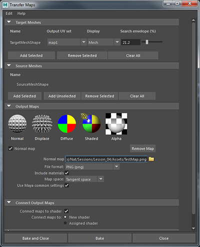
Now we open up Lighting/Shading > Transfer Maps. This window lets you transfer attributes from set of meshes to another, by baking them down into image files. Clear out any geometry in the Target area with the Clear All button, and then assign your target mesh to the Target Meshes area. Repeat for Source areas, making sure to deselect your target and select your source geometry. Now we need to select what kind of maps, so make sure Normal Map is listed and checked off in the area as shown below. This is also a good time to enter a file name and location, as well as scrolling down to Maya Common Output and bumping the resolution to at least 1024. We can always reduce it in Photoshop later.
|
|
Ready to bake our first map?
|
Click Bake, and wait a little while depending on how big your map is and how complicated the geometry is. By default, Maya will make a new shading network and assign it to your target mesh, including a normal map hooked up appropriately. Like bump maps, normal maps can only change the appearance of the mesh by so much, but you should find your target mesh appears to have inherited details from your source and will look much more like it than it did before. This works especially well with small details like wrinkles in clothes, pores on skin, and other things that would be extremely difficult to maintain as full resolution geometry.
|
|
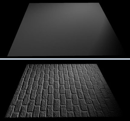
Basic plane with normal map looks great from on top, but from the side we can see that it is still just a plane.
|


