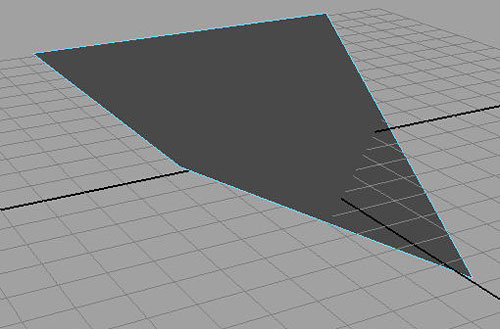
One very common way to model high-res models with polygons now is to work with a lower resolution version of your model, and then let the computer use an algorithm to subdivide it and display it high as if it were a higher resolution mesh. This method is the one I use 90 percent of the time. It balances the total freedom and control of poly modeling that comes with a manageable number of faces, and the need for a high-resolution smooth appearing model that stands up under close ups.
Because this method is so common, Maya has built a mode into the viewport that will automatically display your mesh while under the effects of this subdivision algorthim. To see your mesh as it would appear with smoothing applied, select a mesh and press the "3" key.
|
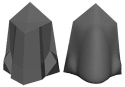
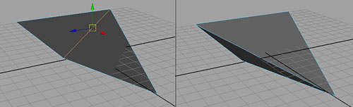
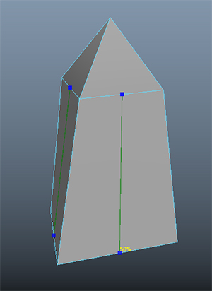
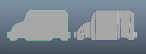
On the left is the actual poly model while on the right is the smooth displayed version. Click to enlarge. |
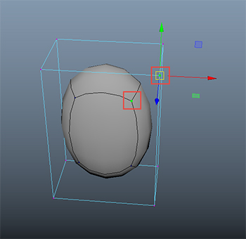
You can work with your model when it is displayed in the smooth preview mode, but you may notice that while hovering over edges and vertices will properly select them, the actual pivot of your manipulator is way over where the original mesh was located. That's because the actual manipulable vertices are still the ones on your non-smoothed version, you are just looking at them differently. You can see an overlay of your original wireframe by pressing "2", or return to normal view by pressing "1". Since flipping back and forth between view modes is so quick, I often just use 1 and 3 when shaping a model, and only use 2 when I am getting a confusing selection.
|
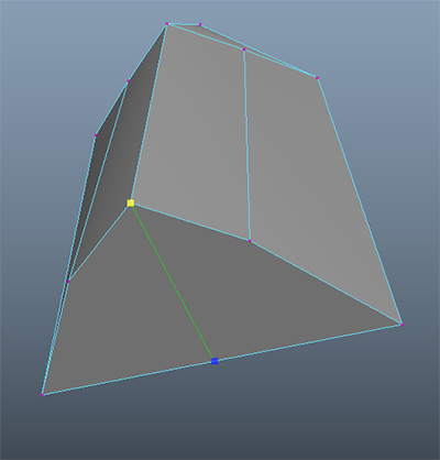
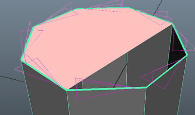
Highlighted vertices are actually the exact same vertex, thats why the manipulator shows up |
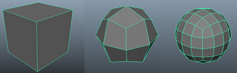
So what is going on here under the hood? Poly smoothing works by taking each face, subdividing it a number of times (4, 16, 64, and so on) and then averaging the position of those new faces according to each adjacent face. To see this, make a poly cube, and perform a Mesh > Smooth action on it. You can see it becomes spheroid. This is because the "influence" of each face is strongest near the
center of the face and progressively weaker near the edges. Since a cube is even, it creates an averaged
version: the sphere. By increasing the number of Divisions in the Channel Box, you can make things smoother and smoother. Usually one or two is sufficient. Stay away from anything higher than 3, as it usually just adds more density than is worthwhile.
|
Smoothed cubes are hardly cubic anymore. |
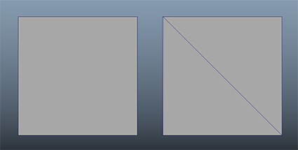
Notice that the object loses volume the smoother it gets. This means that whatever shape your low-res mesh may be, it will become smaller when you smooth it. Also, take a look at the geometry of the cube on the right: its a super even quad grid. Compared to a sphere primitive, this is often a much better place to start modeling a round object, as the mesh is full quads, even size, and good edge flow. Applying a smooth node to your model when its a very roughed out shape is a good way to get quad based geometry to work with going forward.
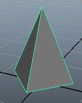
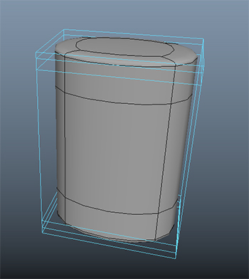
Smooth previews, or smooth nodes both end up with a bit of a conundrum though. Part of the model is wonderfully smooth and contiguous appearing, but what about those areas we wanted sharp? Since smoothing of the mesh is essentially a complicated average of the geometry, we can control it by weighting the average with more geometry where we want it. The closer together the edges are, and the more of them, the sharper the corners will be.
|
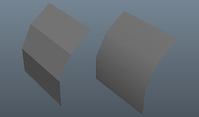
Adding in extra geometry with Multi-Cut edge loops turns the sphere from above into a cylinder.
|
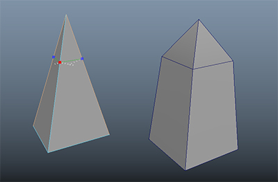
When you are making a higher poly model versus a low-poly model, you might know in advance that you will be using some sort of subdivision on the final geometry. You can plan ahead in your modeling and double up on sharp corners, or use Bevel to create geometry where you want sharp edges. Another option is the Mesh Tools > Offset Edge Loop function, which works much like Insert Edge Loop but places two edges on either side of the selected edge loop. You can always flip back and forth as needed to see the effects of your new geometry, until your character has both the smooth areas and the detail you need.
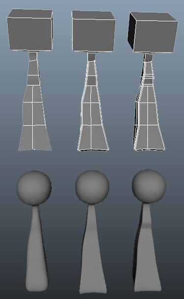 |
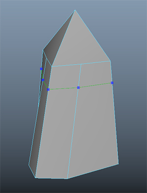
Here a little figure was made for smoothing. It started off as a rectangle, and was molded into this general shape. You can see the head is square, but smoothes into a round shape. To ensure a squarer body, detail was beveled into the corners. Then, to add detail to the "chest" of the character, Insert Edge Loop added a few more cross sections to get a defined curve. |
When you know your model's final destination is not going to be staying in Maya (Or exporting as a point cache), you can use a feature of Maya subdivision algorithms that let you sharpen corners without adding extra geometry, called Creasing. Creasing is a way of weighting edges in that averaging algorthim, so that you don't need to mess with a bunch of bevels or edge loops in the corners.
Using Mesh Tools > Crease, select and edge and MMB Drag to increase or decrease the level of weight an edge or vertex has. Creases are denoted by heavily shaded edges, and you will find that how an edge or vertex affects the mesh is also related to how the components connecting to it are weighted.
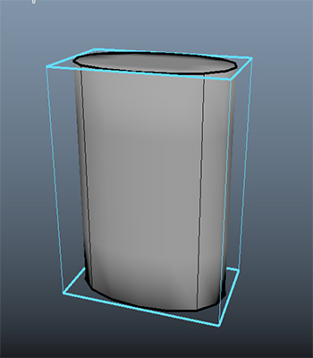 |
The same basic sphere from before, but creased. This cylinder looks very similar to the version with extra geometry. |
Before we get started on characters, let me make a small disclaimer: There are hundreds, if not thousands of ways to model. I will go so far as to say that there is one way to model for every modeler. I'm going to show you how I like to build humanoid characters, and this process is similar to how I was taught. I think it's a good starting point because you will learn to adjust your technique as you progress, just like I did. New technologies will be developed and from that new challenges will broaden the way you need to think about these things. There is no one right way, though there are certainly plenty of wrong ways (insert ominous thunder). For now, lets just shoot for good results.
|
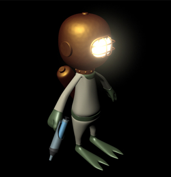
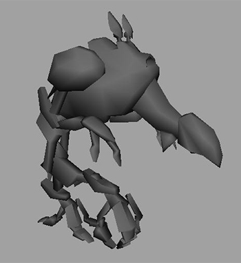
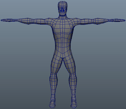
This funny little guy was modeled with polygons and smoothed, using only tools discussed in this lecture. (He was then textured using tools we'll explore in Lecture Four. Ignore the man behind the curtain.)
|
One thing to keep in mind in all modeling: If no one ever sees it, and nothing ever touches it, don't model it. This means you don't need to model the engines of most cars, the insides of most clocks, and frequently, the entire bodies of clothed characters. A good deal of work can be avoided by not spending your time doing unnecessary tasks. If a character is wearing a jacket, you don't need to worry about his upper arms. If a character has a big metal piece of armor over his shoulder, you may not need to attach the shoulder smoothly. Long skirts save the work in connecting legs to hips—the list can go on.
|
|
The simple segmented design of this robot was chosen to save poly count at the joints and ease
deformation.
|
Characters are usually everyone's favorite thing to model. We are going to go quickly over the process of putting together a humanoid model. This will be your exercise for this lecture as well, so you may wish to read that first, and keep it in mind or follow along as you go.
To start, you need to know what you are working on. Humanoids are complicated, and they are tricky. We expect to see certain things. Small adjustments can make a person seem alien and creepy or make them have character and warmth. People spend so much time looking at people that they are really very good at detecting things that are unusual. This means anything that remotely looks like a
person requires a higher degree of precision and attention to be successful.
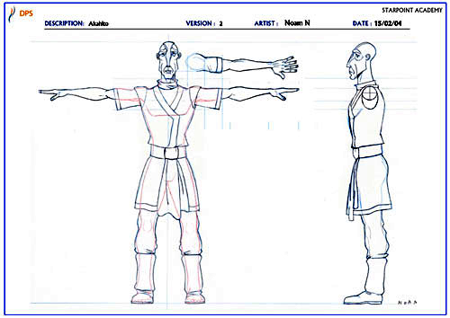
In order to ensure your proportions and details get put together right, it helps to have a reference image right there with you in Maya. First, you need to put together a few sketches of your character from different angles. Front and side at the minimum. Back, top, and three-quarters helps too. Character sheets with these views are freely available on the web, as well as generic humanoid forms:
|
This is the character sheet I was given to model the character you've seen so far. Click to enlarge.
|
To bring your images into Maya, go to your front view. From the View menu (at the top of the front view window), choose Image Plane > Import Image. An image object will appear in your scene. If you open up the attribute editor (View > Image Plane > Image Plane Attributes), you can adjust its size, visibility from other cameras, transparency (called Alpha Gain), and so forth. If you de-select it by accident, the only way to re-select it easily is by going back into the View menu of the view you placed it in, and choosing Image Plane > Image Plane Attributes again.
Image planes are great references to have, because you can line up your geometry and outlines precisely against them, taking some of the guesswork out of tricky models. The act of using an image plane as a reference is referred to as rotoscoping because it is similar to the traditional animation technique of the same name. Rotoscoping traditionally means drawing over a frame of film to produce your image (such as the music video for A-ha, Take on Me, Google it).
|
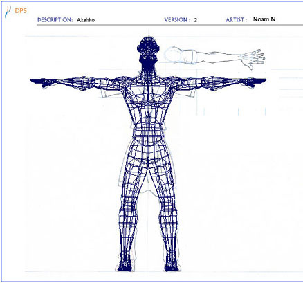
This shows the model laid over the reference. This helps ensure accuracy in the drawing. You can see a few small deviations made after the model was finished (longer arms, for instance). Click to enlarge.
|
The Chicken or the Egg? Creation Order
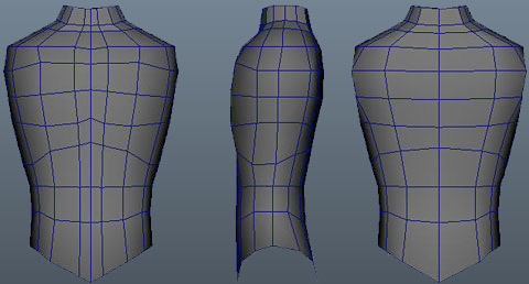
With a model like a humanoid, it's not always clear where to start, and what order to do things in. I like starting with the torso, because it is the center of the model. As with most objects, I start with a primitive of suitable shape: usually a cylinder with 8-12 cross-sections (depending on how detailed I think the character is going to be). I scale, and then tweak the cylinder into place at the torso. It helps to turn symmetry in the Modeling Tookit while working on a character, this way you don't have to alter both sides of your model.
|
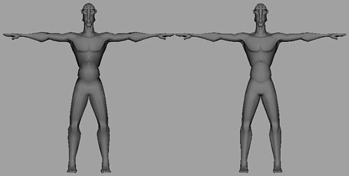
Front, side, rear of the rough torso. Notice that the general curves of the edges match the body, even before they are refined or attached to anything.
|
Don't worry too much about the areas near the shoulders and neck. They will sort themselves out when we have those parts.
I usually build the arms separately, then attach them. I do this because I find it's easier to not worry about the joint, and instead focus on the arm. Then, once I have the arm the way I want, I can bring it over and figure out how to attach things without mangling my hard work.
I usually construct my arms starting with hexagonal or octagonal cylinders. Remember, in either low poly modeling or modeling for smoothing, start with less and add in. In constructing your arms, take care to insert some cross sections with Multi-Cut near the elbow and wrists to ensure proper bending later. Although we will not be rigging these characters for animation in this course, it never hurts to start good habits early.
|
Arms with flipper hands. Note the cross sections deformation (distortion of the model when it is animated) much later.
|
Now that we have the arms, I put them in place on either side of the torso, and need to join them. There are a few ways to do this. The first step is to perform the Mesh > Combine function on the two pieces. This makes them one poly object. Then pull vertices in the arm and torso to sort of line up with
each other as best you can.
If both objects have solid caps with the same number of faces (unlikely unless you've planned it that way) you can use the Bridge function by selecting the relevant faces and clicking Bridge in the Toolkit.
The second and most reliable way is to create a hole in the torso by deleting any faces the arm will cover up. You can then can use Append to Polygon to bridge the gap. If you don't want to add in an extra ring of geometry, you can use Target Weld in the toolkit. This tool works by click-dragging one edge or vertex to another where the two will be joined up. Both edges must be border edges for this to produce good geometry.
|
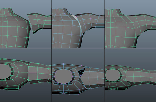
This is an elaborate process. First, the pieces are joined. Then they are adjusted to fit each other better and internal faces are deleted. Next Append to Poly, Merge, or Target Weld are used to close the gap. Click to enlarge.
|
Once the areas are combined, I use Multi-Cut and re-tool the area to look nicer. You'll want to make sure that you've made a good set of quad geometry in the connections. Getting your edges to look sensible is not only aesthetically pleasing, it helps later if the character has to move. Try to put some concentric circles around the neck, and running over the shoulder. Contiguous edges are your friend.
A tool that really helps with adjusting organic models is Soft Selection. You may have seen the tab in the Modeling Tookit already. Soft select means that whatever transformations you apply to a component are applied 100% to that component, but also to everything in a radius, falling away to zero. You can adjust the size of the radius (and the profile) in the toolkit, or by holding "B" and MMBdragging back and forth to increase or decrease radius. There is a visual display of how strongly an area is affected by shading the components with a heat map, which makes it easy to see when your radius is affecting the area you need.
|
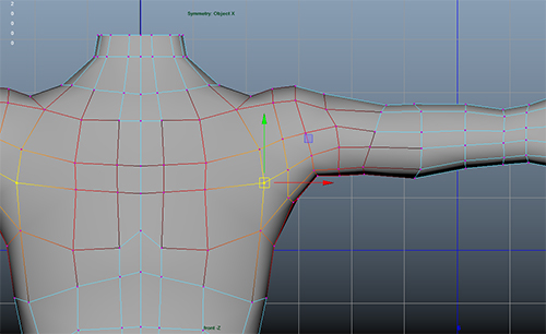
After a bit of point pulling, Multi-Cut, and Soft Select the shoulder looks much better.
Click to enlarge.
|
You may have noticed that Merging up your geometry has ruined the symmetry of your model. This is easily fixed before moving on with a quick Mesh > Mirror. Be sure to have the midline of your model at zero on the X axis, select Cut and Combine With Original as options, and mirror away. Now your symmetry is restored!
To attach the legs, I usually form an angle at the hips first. This is easily done by rotating the top crosssection appropriately, then adjusting the one below that a little less, and so forth down the leg. Once the
leg is properly shaped, it can then be joined to the torso. This ensures the direction of my edges are optimal ahead of time. The groin is tricky since you have two cylinders coming into one area, and in some cases you will be best suited connecting the inside edges of the legs to each other instead of the torso. It's best to attach both legs before worrying about the best edge flow and eliminating odd shaped polygons.
If your character is low poly, try not to model things like toes, even if they will be visible. Sock feet can be embellished with textures or adjustments, and people tend to concentrate on face and hands more, so detail is better spent there. Once your leg is constructed, attach it to the hips (if appropriate) and move on to the head!
|
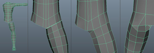
Just like the arm, position the leg, join the vertices, and then polish it up. You may need to mirror your model before everything is done to help get the groin right. Click to enlarge.
|
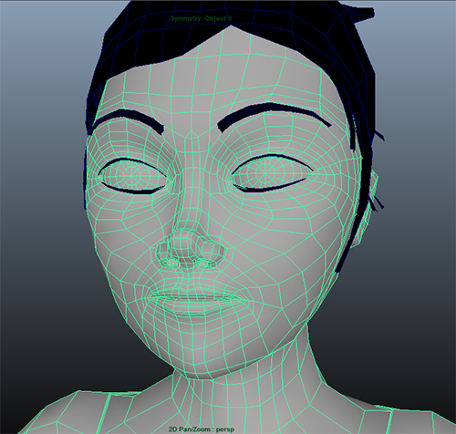
Every head is different, which makes it difficult to say how to model one. For a low poly head, I usually start with subidivided cube, and roughly shape it before extruding ears and noses out, and perhaps a mouth in. Then I add any important details with Multi-Cut, getting my edges aligned correctly. A higher poly face is the subject of a whole lesson or more, as it involves a significant
amount of re-arranging edges for good animation. Just for reference, below is a face of a character who's poly budget was 10,000 polygons. Notice the loops around the eyes and mouth, instead of a simple grid. You won't need to do anything this detailed for the exercise, but keep this in mind if you start to add in some facial detail.
|
Facial modeling is a complex topic into itself, so try to keep the heads of your first few characters simple. |
Once the parts are all attached, I check my poly count and add details. Adjusting proportions (don't forget Soft Select!) should be done at this phase. Once more, I go over the model and check to make sure I don't have any 3 or 5 edge faces that I don't need. If there are any accessories or extras, like pouches, hats, weapons, badges, and so forth, I build them separately at the end.
|
Final Character. I decided the torso was too skinny at the end, and so I fattened him up a bit. I also tacked on a very rudimentary face, mostly to include the giant nose made earlier.
|
The time will come for all of you: Your model is finished, it's beautiful—flawless in every way. Every vertex exquisitely crafted and placed with both artistic verve and mathematical precision. And then the memo comes in: "Looks great, but it's a bit heavy, can you reduce the poly count by say... 40 percent?" Tears will flow.
So, what to do? Sometimes, things just don't work as dense as we made them. I've made pieces of geometry that looked pretty low poly, and I thought I was pretty clever. But then when it was duplicated a few hundred times in a scene, things got sluggish. So you take it under the knife.
Reducing poly count is a tricky business, and involves a combination of elimination, merging, and unfortunately, remaking. Let's start with the worst case: remaking.
Sometimes an object has a simple shape, but just too much density. Maybe its a box that was beveled way too aggressively, or a sphere that just had its cross sections set way too high. Rather than selecting and deleting every other section from the sphere, its often faster just to leave the existing object there as a template, make a new lower poly to overlap, and the delete the original. You can even use Snap tools to ensure your corners and so for are in exactly the same places.
|
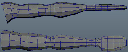
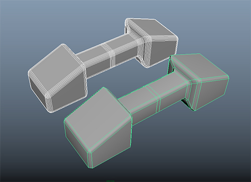
Simple shapes are generally best remade. This handle is reduced from 2000 polygons to only 200.
|
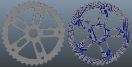
Eliminating unnecessary components is the next step. Of course, its easy to feel that all our components are necessary, but some are just more necessary than others. Components that define silhouettes are much more important than components that simply make a subtle curve or bit of shading clearer. Going over your model and removing unnecessary edge loops is the fastest way to significantly
drop the poly count. Double-click on an edge to automatically select an edge loop, and be sure to use "Delete Edge" so that you don't orphan any vertices, otherwise your poly count won't drop at all!
|
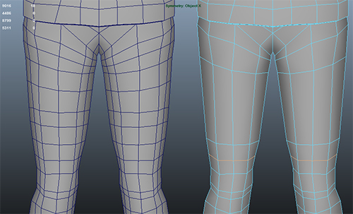
On the left the original waitress's legs, on the right edge loops that dont change the curvature much have been selected and deleted to reduce the poly count.
|
Sometimes an edge loop is very important on one side of the model, but not on the other side. This is frequently the case with the knee, for instance. Other times you might have a larger number of edge loops coming into a smaller number, like where the arm joins the shoulder. In these cases you need to do a little more than just delete edges, since you'll end up with a partial loop that terminates into a 5 or 3 sided face. Sometimes that's OK, particularly if you are staying in Maya and/or its in a hard to see spot, but other times you'll need to fix it with quads.
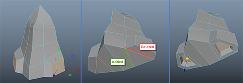
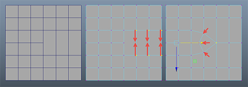
Take the simplified example below. I need to remove an edge from one half of the plane, so I select those edges and delete them. You'll notice that I get one five-sided face and two four sided. The solution is to merge down the vertices (Edit Mesh > Merge to Center) on top and bottom of my new five-sided face, all the way down the row where our edge was. Then adjust the placement of the remaining vertices to soften out the transition. You can also use Target Weld on edges or vertices to eliminate extra faces if you find it simpler.
|
Eliminating only part of an edge loop takes some care to preserve good geometry habits.
|