The most common type of geometry used in Maya is polygonal geometry. As mentioned in Lesson 1,
polygonal geometry is made up of vertices and faces, and the edges between them. Many polygons put
together form approximations of smooth surfaces and have extremely flexible arrangements to suit
almost any need. There is another type of geometry based off of smooth curves and surfaces called
NURBS, but it uses are somewhat limited to industrial modeling and character rigging purposes, so we
will focus only on polygonal geometry.
We can manipulate the shapes of our polygons far beyond the basic primitive forms: adding and
subtracting, subdividing, mirroring, combining, smoothing polygons and more, until we get to the final
desired form.
Before we start this lesson, make sure you have selected Modeling from the top left drop down menu so that the relevant menus and tools will be visible.
|
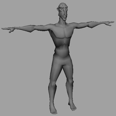
This medium resolution alien was made with polygons. |
In order to get into manipulating objects on a more detailed level, we will frequently want to use a fairly new tool in Maya, the Modeling Toolkit. The toolkit is a window that by default shares space with the Channel Box, so is easily acessible by clicking the tab on the far right edge of the screen.
The toolkit contains a combination of selection, manipulation, and editing tools, as well as easy
access to some tool settings and preferences. All of the information here can be accessed via the menus
or other shortcuts, but Autodesk is clearly focusing on making this the central location for polygon
modeling, so over the course of Lessons 2 and 3, I will frequently be referencing this tab. Open it now
and take a quick look, but don't worry if it doesn't make a whole lot of sense yet.
Finding Out What You're Made Of
Any model in Maya is made from smaller pieces known as components. What these components are depends on what type of object they come from.
A polygon object consists of vertices, faces, and edges:
 |
|
 |
| |
- Vertex: A one-dimensional point in space, also known as a point in Maya.
- Edge: A line defined between two vertices.
- Face: An enclosed polygon defined by three or more edges.
|
|
 |
|
 |
These polygon objects are all intertwined, as you can see: If you move a vertex, any edges connected to (defined by) that vertex, and any faces connected to it, will move as well. If you move an edge, both vertices will move with it. Moving a face will likewise move all vertices around the face.
To manipulate these components, you need to enter Component mode. By default, Maya starts in Object mode. You will switch between modes often, but there are several quick ways to do so.
While Object mode lets you move objects about in space, Component mode lets you move the parts that make up those objects. To get into Component mode, open the Modeling toolkit and look at the top section. You will see a series of buttons that represent the different geometry types. The one on the far left represents object mode, what you have been working in so far. Selecting any of the middle 3, or the
big Multi-Component button will enter you into component mode. From left to right they are: Object Mode, Vertices, Edges, Faces, and UV. Multi Component is a mode unique to the toolkit that lets you select any of the middle three types. We will ignore the UV option until Lesson 4.
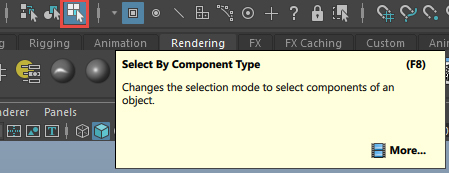
The keyboard shortcut to get into Component mode is to press F8 (Fn+F8 on Mac). This toggles back
and for the between Object Mode and the last type of component selection you used. You may notice in
doing this, or using the Toolkit that on your Status Line (under the menus) some buttons have changed.
These buttons can be used much like the ones in the toolkit to select a broader variety of components,
or when the toolkit isn't open.
|
| Component selection: The
two you'll need most are Points (1) and Faces (2). |
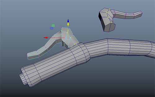
Once we are in our desired mode, we can actually get to the business of shaping our objects. If you havent already, Create a new primitve in Object mode, press 5 to shade it, then press the Multi- Component button in the Toolkit to switch to Component mode. Mouse over the various parts of the object and notice how the highlighted areas change. Try selecting a face, or some faces (Use Shift-click to add to your selection) then press W to move it around a bit.
|
Component manipulation.
Eight faces are selected and moved outward. |
Try selecting some vertices and edges and wiggle them around a bit as well. If you are having trouble selecting a specific element, you can exit Multi-Component mode by selecting a single desired component type from the Toolkit. You can also change component mode by holding right-click over your object to bring up contextual menus in Maya called Marking Menus.
You can then select the component type you want to manipulate. You can do this from Object mode too! You may find you prefer this method of selection to making the trip to the Tookit, so give both a shot. Continue making some basic objects and transforming their components a bit before reading on.
Many artists start their polygonal models by choosing a primitive to match the shape and size of an object, and then pulling and pushing components into a final shape, like a clay model. Of course, while there's a lot you can do with just pulling components around, you'll need to be able to add and subtract components from an object to get any really complicated shape. Well, alright, to be fair you could create a 50,000 point sphere and then pull each vertex where you wanted it. I'm sure there are some people for whom that would earn a creepy sort of respect. But for the rest of us sane folks, there are luckily other options.
Manipulating Faces
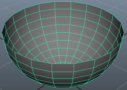
Deleting: First and foremost, one powerful option is deleting faces: Select a face, or faces, and press Delete.
|
|
This sphere has had the upper two thirds of its faces selected and deleted, so that it now resembles a bowl.
|
If you have put a hole in an object by deleting faces, and wish to patch it over, you can select your Object (in object mode) or the surrounding faces on your object (in Component mode) and use Mesh > Fill Hole. Wonderful! Moving on...
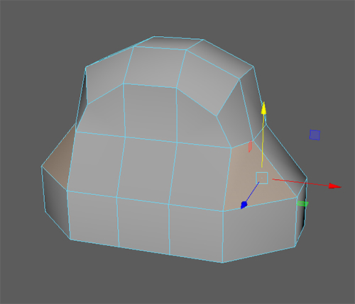
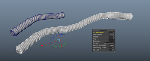
Mirroring: As we get into more and more complicated actions on our model, it frequently is desirable to have the same action happen on both sides, particularly with vehicles and characters. The Modeling Toolkit contains a Symmetry function which will automatically select components on the opposite side
of the model.
You can only be symmetric across one axis at a time, but commonly this will be the X axis, for left/right symmetry. Most actions performed on the selected components, such as transformations or additions will be properly flipped across the axis. If your object is symmetric but not at the origin, use Object based modes. If your mesh is symmetric across the origin but for some reason the pivot point of your mesh is not in the plane of symmetry, use World based modes. Beware though, that if the model is somehow made un-symmetrical by an action that this symmetry will stop working and you will need to use the Edit Mesh > Symmetrize function to restore symmetry, or do things manually
|
Using the symmetry option automatically performs actions on the other side of your model. |
Extrusions: Modeling with polygons is often compared to modeling with clay. The Extrude function is a lot like pulling on your model to extend the geometry. Only in Maya, the volume doesn't need to be preserved (meaning your model doesn't get skinnier the more you tug on it, it just gets bigger). The Extrude
function can be used to add limbs, rivets, noses, divots, antennas, tentacles, openings, and more.
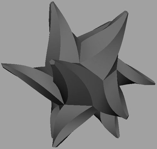
|
This odd shape is the result
of an extrude on all the faces of a dodecahedral platonic solid. The
options were set to create the tapering spiral instead of the
normal results. |
"But how can we too enjoy the wonderful benefits of extrude?" you ask? To extrude, here is the routine:
|
|
|
| |
1. Select a face (or multiple faces).
2. Click the Extrude Button on the Modeling Toolkit, or use the shortcut Ctrl-e.
3. Use the manipulator and option box that appears to move the new face away from the old.
4. If you want to continue to extrude, press G. This repeats the last action. |
|
|
|
|
Since this is important, let's practice it a moment.

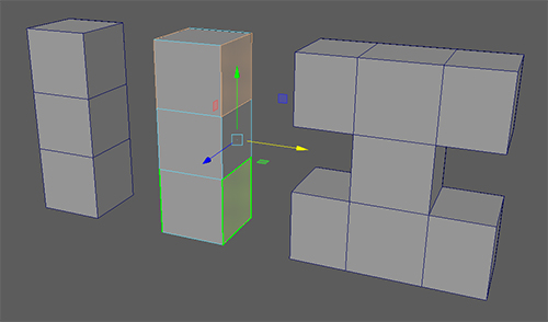
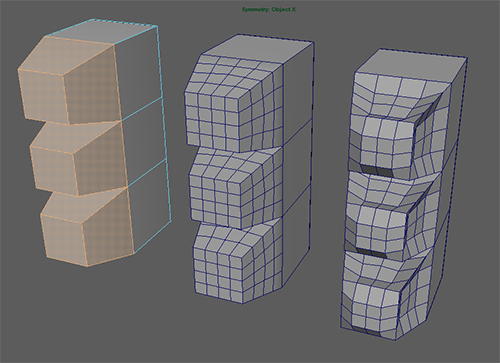
Extrusion Without Confusion
Make a cube, and select the top face. Extrude, and then drag it straight up (either in a side view, or using the Y axis arrow on the manipulator). Press
G to make a third section and space it evenly away from the other two, like in the diagram below. Now select the
two on the top and bottom, making sure symmetry correctly selects the far side, as shown in the middle
below, and extrude once more. Remember to hold Shift while clicking to select multiple faces. Without
deselecting anything, drag the manipulator away from the sides. You should get an "I" shape:
The manipulator that appears when you extrude moves the new face/faces relative to the direction they are facing, instead of relative to the world space or object space. This means the blue axis is always "away" from the surface. It also means you can scale the new faces. Click and drag on the square in the center of the extrude manipulator to uniformly scale the faces.
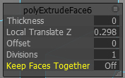
Additionally, you can extrude multiple faces at once. If you do this, you can either keep the faces together, which is useful for raising a platform or building out of the ground, or you can keep them separate, which is useful for making bumps or spikes. This is changed with the drop down menu in the option box that appears with each extrude.
|
Faces extruded separately (left) and together (right). |
You can adjust the rest of extrude options in the pop up, or by selecting the small box next to the Edit Mesh > Extrude menu option. This is the option box, where many tools let you change settings and behaviors.
 |
The pop up box contains the most commonly adjusted extrude settings, you can add more with the tiny menu in the right, or by checking the tool options from the menu. |
If you find you need to perform a common or repetitive task with extrudes, these options can make your life easier. Save the monkey work for the computer. And the monkeys, I suppose.
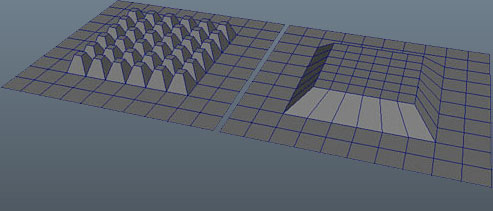
Adding Faces Frequently, we will want to add a little bit of detail into a model in a particular area. The last simple face tool we'll talk about today is Extrude is great for adding detail around the outside of an object, but what if you wanted to add detail in the middle?
The simplest way to do this is to use the Add Divisions button in the Toolkit. Add Divisions subdivides the selected faces any number of times, increasing the number of faces you have to work with. You can then drag the new components around to add detail into the model.
|
Subdividing your geometry is the simplest way to increase the available geometry to work with. |
Since this method is the simplest, it also has the least control. If adding divisions create more edges than you wanted in one direction, you can always select and delete the extra components as discussed below. In Lesson 3 we will explore options for adding density without this extra step.
Manipulating Edges and Vertices
The edge functions are much like the face functions. That is, you can extrude, delete, transform, and more. I categorize them separately because they are a distinct change in tactic from the clay/volume based approach of moving around faces
Consider this: Think of your object as a balloon or clay sculpture. Extruding a face is like stretching that around the shell to whatever shape you want. No matter how many times you extrude a face, you will preserve that "shell." In other words, extruding from a sphere doesn't put a hole in it or add any strange joints. However, if you select and extrude an edge (Edit Mesh > Extrude), you suddenly have a two-dimensional "tab" hanging off your shell. This tab has no volume, has a razor edge, and is "glued" to the surface where two perpendicular surface planes come together. This can cause weird looking, or weird behaving objects.
Stay away from this kind of edge extrusion in general, and only extrude open, or border edges.
|
These flaps are edges extruded from an enclosed object. This is often a bad idea. |
However, there are some advantages to extruding edges. If you think of your object as a paper maché
model instead of a clay sculpture, extruding an edge can be akin to laying a new piece of paper on a
model. For objects with holes in them, extruding the edges around the holes is a good way to build up
(and out) new pieces of geometry.
The difference between the two approaches is sometimes referred to as volume-based modeling vs.
edge-based modeling. Some people prefer one to the other. For me, it depends on the task, and it often
doesn't matter which approach I use. For instance, there is no difference between deleting a face and
then extruding the edges, and extruding the face up first then deleting the new face.
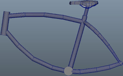
|
The bike frame shown here can be made by extruding the end cap of a cylinder, or by extruding the edges if there is no end cap. |
Removing Edges
Speaking of deleting, deleting edges is a bit funny, and caused me some frustration at first. Maya
helpfully won't let you use the Delete key to delete an edge in such a way that it would break an object
open. Basically, you can delete an "inside" edge, but you can't delete an "outside" edge.
|
On the left, an inside edge is selected, and is deletable. On the right, after the deletion, all the edges are border edges, and cannot be deleted. |
Also, if you press Delete to delete an edge, Maya just removes that edge, and leaves the vertices
associated with it. Sometimes you'll want to delete an edge and the vertices at once. For that, there is
the Delete Edge function (Ctrl+Del, or Edit Mesh > Delete Edge/Vertex). This removes an edge and
any vertices that make up the edge, but will not create a hole in your geometry.
 |
On the left, just
an edge is removed. On the right, the vertices for that edge
are also removed,
resulting in this wedge shape. |
Lastly, be careful when using Delete: It may leave points you don't realize are there. This plane had all its internal edges removed with the Delete key, and now has a bunch of superfluous vertices that should be removed.
|
This square of vertices was made by deleting all the inside edges of a plane with Delete instead of Delete Edge. |
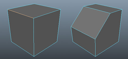
Bevels One of the biggest issues in preventing an object from looking chunky and computer generated is to
ensure it doesn't have razor-sharp edges. A primitive cube has a single pixel corner. This corner will be
aliased (jagged), appear sharp, and won't reflect light or pick up highlights like it should. Almost any
object in the real world has a bit of a curve to its corner. Metal plates, wooden desks, the facets on a
pencil: all are slightly rounded.
These slightly rounded corners can be reproduced using the bevel tool. The bevel function automatically puts extra geometry detail into corners so that they appear smoother. Some shapes would be very hard to make without them.
|
A difficult shape to make evenly by hand. |
This object starts as a cube. Bevels are applied to whatever edge you have selected. It's best to
think ahead and select all your edges that you wish to bevel, because beveling one at a time is hard to
adjust and can produce funny results. And no, not ha-ha funny, unless you think untangling a mass of
poorly constructed geometry is a big giggle.
Since we want one corner in our cube cut off, I select one edge in Component mode (F8 Windows, Fn+F8 Mac), and then choose click the Bevel button on the Toolkit, or choose Edit Mesh > Bevel.
|
First bevel, on just one edge. |
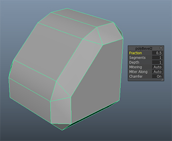
Like the extrude function, Bevel pops up a little window showing your bevel inputs. You can adjust them here before movin on. By default, the bevel is a single face placed halfway in between the edges at a 45 degree angle. We'll leave it there for now. Now, I select the whole object, and perform a second bevel. When the whole object is selected, this action bevels every edge.
|
To increase the smooth appearance of a bevel, increase the number of segments. To increase or decrease the size of the bevel (the radius of the curve, essentially) adjust the fraction. |
A Quick Note About Object History
Bevel is one of the first operations we have learned that might want to be edited after the fact. Remember in Lesson 1 when you selected the inputs to the basic primitives to adjust the number of cross sections or radius? Well, every action you apply to a mesh is by default stored as a chain of nodes. The position of the mesh is a node, the shape of your mesh is a node, and the inputs that determine the shape of the mesh are also nodes.
We will talk more about history in a moment, but for now know that you can get access to these
previous objects by selecting them in the Inputs section of the Channel box, and adjusting them. The
more you have done since the action, the more likely that adjusting a node in the middle of the chain is
going to cause problems, so this is mostly for making quick adjustments to recent actions.
Booleans let you take two polygon meshes and make a new object out of them. Kind of like taking your brother's toys and gluing them to your toys, only with less fighting. Booleans can be used to add
or subtract objects, make holes, trim bits off objects, and so forth. If you've used Adobe Illustrator's
Pathfinder palette, this idea should be familiar.
Booleans work their magic on the overlapping area of two objects.
There are three types of Booleans:
|
|
|
| |
-
Union: Merges two objects into one. Wherever they overlap, extra geometry is deleted to ensure no internal faces.
-
Difference: Removes the second object selected from the first object. Any overlapping area is deleted, as well as the entire second object. Selection order matters.
-
Intersection: Deletes the two objects, but leaves the overlapping area as a new object.
|
|
|
|
|
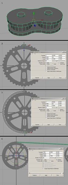
Applied Example: Bike Parts
Let's go back to the bike I was building earlier and use it to explore some of the techniques I've covered so far. Follow along if you'd like.
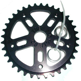
Say I wanted to make some gears for my bike. Gears are a pretty complicated shape, so I'll need some reference for accuracy. A quick Google search gets me a good shot:
Going way back to Lecture One, you'll recall a good way to start is
with a primitive of the same rough shape. This looks like a nice flat
cylinder
to me. Since
I can see I'm going to need a lot of detail around the edge, I'm going
to add a lot of cross-sections to my cylinder. To keep things simple,
I'm going to make only one face on the cap, like so:
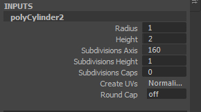
|
These are the settings in my
channels box. |
Why 160? I have about 40 teeth on this gear. If I were doing this for a design spec, I'd have to count exactly. If it were for a game or some other entertainment, it's probably not important how many teeth it has, so long as it looks like a gear. Since I'll want a few faces per tooth, let's say four, I chose 160 divisions. This will not be a low poly gear, but it won't be a real photo either. Good for a minor detail on a major object, perhaps.
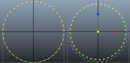
Next, I select every other pair of vertices and scale them in. To
make your life a little easier, use the Lasso
tool (found just below the Select tool in the toolbox on the left) and
just work your way around.
Since
the selection is centered, the vertices scale down evenly and it
makes a nice gear
shape.
|
Gear with every other pair
of vertices selected (left) and scaled down (right). |
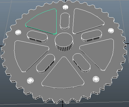
So far so good—let's move on to the cut outs. We have basically
three shapes here: circles, round triangle things, and
ovals.
We can't
really extrude to make these shapes, and besides, our extrude would
have way too many faces because our gear is so dense, so I'm going
to go make these shapes out of some primitives. These primitives
should be at least as thick as the gear, so it is easy to intersect
the two
completely.
The oval is easy: Just take a cylinder, grab one side and move it
out, and make sure the middle is straight. The circle is even
easier: It's just a cylinder. The triangle is a bit trickier. There
are some tools we haven't learned yet that would make it easier, but
for now I'll just make a new cylinder.
As with the oval, I go to the top
view and select some points—in this case, about a third (180
degrees worth) and pull them into three corners. Now I have a
straight-edged triangle with rounded corners. I then use the vertices
near the two corners and drag them out along one edge to round it out
a bit.
|
Oval and triangle shapes needed
for the gear cut-outs |
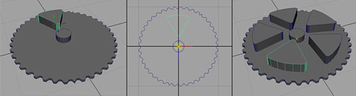
Now it's time to place our Boolean objects so they overlap where
we want the holes to be. I scale the triangle and put it into place.
Now, however, I need four more cut outs evenly spaced around. To keep this accurate,
I'm going to use a little trick: If I move the center point to the
center of the gear, I can rotate them "around" the gear and
not worry about eyeballing the placement.
Since
a circle is 360 degrees, each gear will be rotated 72 degrees away
from the
next.
I
press Insert (Home on a Mac) to
move the pivot point to the middle (like we did with Big Ben in Lecture
One). I duplicate it four times (Ctrl+D, Command+D on a Mac) and then
type in some rotation
values,
and voila!
A quick repeat with the other elements, and I'm ready to start Booleaning.
To Boolean. Booleanize. Er... cut holes.
You can continue on using your own gear, or you can download mine in the course download area. All that's left is to select my gear, select one of the Boolean objects (these need to be done one at a time) and choose Boolean from the Toolkit. The selection order matters, because if I select the other way, it will subtract the gear from my Booleans, and who wants that? Change the boolean settings to Difference. Repeat for the rest of the Booleans, one at a time, and suddenly we have a gear!
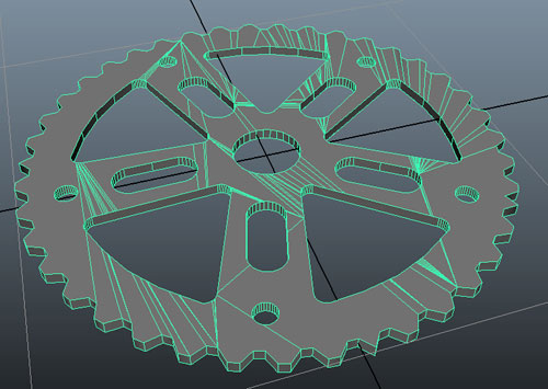 |
Gear finished |
To Boolean or Not to Boolean?
A valid question, considering Booleans are a binary operation (it's either intersecting or not). The
point is, it's not always best to use Booleans to make your shapes. Booleans tend to produce less
efficient geometry. You'll notice the gear above has a lot of really funky geometry in it. Bad geometry
like that shades funny, deforms worse, and is hard to work with. Booleans provide great shortcuts and sometimes are necessary, but be on the lookout for ways around
them. For instance, if you wanted to make a hole in the barrel of a gun, you wouldn't need to use a
Boolean cylinder to cut it out. Just extrude the barrel, scale it down slightly, and extrude it back inside
itself.
 |
|
This goofy little tank was made for some pre-rendered graphics. The barrel is just one cylinder extruded over and over.
|
No Names and Dates, But Still Tricky
Remember that little bit about object history from the Bevels section? Me neither. It was so long ago!
Object history is a feature of Maya that is a bit mysterious. Essentially, Maya keeps track of not only
what each object looks like, but also how it got to look like that. If I make a sphere and scale it, Maya
knows that first it was a sphere, and then it was scaled. If I make a Boolean object, Maya knows that
that object is actually the sum (or difference) of two objects, and continues to track them separately.
This means you can use the inputs like with the primitives and bevels to go back and make
adjustments.
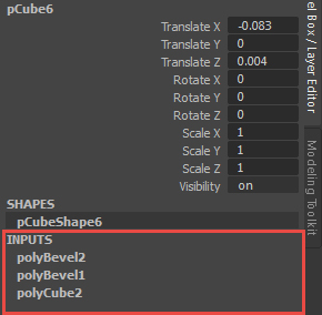
It also means that unless you keep an eye on things, your objects can get hugely complicated. The history of an object is displayed (in part) in the Channel Box under the INPUTS heading. These are all the nodes (parts of Maya data) that are currently affecting this object.
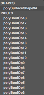 |
List of Inputs of the gear
|
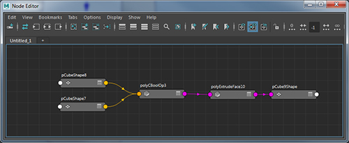
Inputs are listed most recently to least recently. The cylinder node is at the bottom (the one we set to 160 divisions and so forth), then the tweak we made (scaling in the points), and then all the Booleans at the top.
How Maya keeps track of what is affecting what, and how its all connected is controlled by something called the Node Graph (Windows > Node Editor) The node graph is a bit like looking under the hood of a car. There is quite a lot going on, and its usually best left to a professional, but if you know what you are doing you can save yourself quite a bit of trouble. We aren't going to worry about using or editing
the node graph, but I think it's useful to understand whats going on when you look at that set of inputs.
|
The node graph shows nodes as gray windows and connections as various colored arrows. |
Pictured above is the simplified history of an object. Two polyCubes have been combined into a boolean, then an extrude action has been performed, and the final output is pCube9shape. The location of pCube9shape in the scene would be determined by a transformation node (what we manipulate with the transform tools).
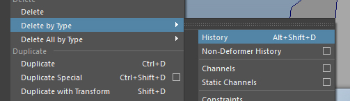
When the history of an object becomes too long and cumbersome, particularly when stacking up nodes like boolean, combine, and some types of deformers, performance and stabilty can suffer. To clear out the history and bake the whole graph into what you have right now, you can select and object and choose Edit > Delete by Type > History, or press Alt+Shift+D. This resets your current object to the new base object and lets you build up from there again.
I mention history now because it can be an important tool and it can also be a headache. Sometimes things won't work quite as expected when an object has strange inputs. Sometimes changes to inputs will result in weird-looking things. Keeping an eye on the history is a good way of getting used to these concepts and solving problems.